Rick’s gotta save room for more weed.
- 42 Posts
- 1.25K Comments
Joined 2 years ago
Cake day: February 15th, 2024
You are not logged in. If you use a Fediverse account that is able to follow users, you can follow this user.
I have a halfway decent woodworking setup, plus a 3D printer and a cheap laser, but metalworking is just not really an option. The space dedication, plus the oils and the fire hazards and the scraps/shavings/slivers/chaff/god-knows-what-else all being completely incompatible with sharing a space with the rest of it. Sigh, just not likely to happen until and unless I can get in with the makerspace mafia. I am thinking of trying to figure out designing for mills and using metal-bending workbenches in CAD, though, and sending more designs off to be fabbed.

I call it replicator chicken. It looks perfect, striking you as having been cooked in pristine oil, is consistent and properly fried, but then when you taste it you get the world’s blandest recipe. It’s really like a well-meaning computer’s idea of chicken tenders.
The sauce is decent, and utterly necessary, but it’s really not worth it, even within the space of fast-casual chicken fingers. I prefer Layne’s or even Zaxby’s.

 33·4 days ago
I mean, why else do we think this was the final straw?
 20·7 days ago
Then there’s the timing of the announcement that Barron is ineligible to serve because he’s too tall or some shit
I had to look that up. Apparently the limit is 6’8", and they claim he’s 6’9". Now, the kid is clearly a tall motherfucker, but how much y’all wanna bet he actually tops out at 6’7"? (6’9" is 205.74cm)
 2·7 days ago
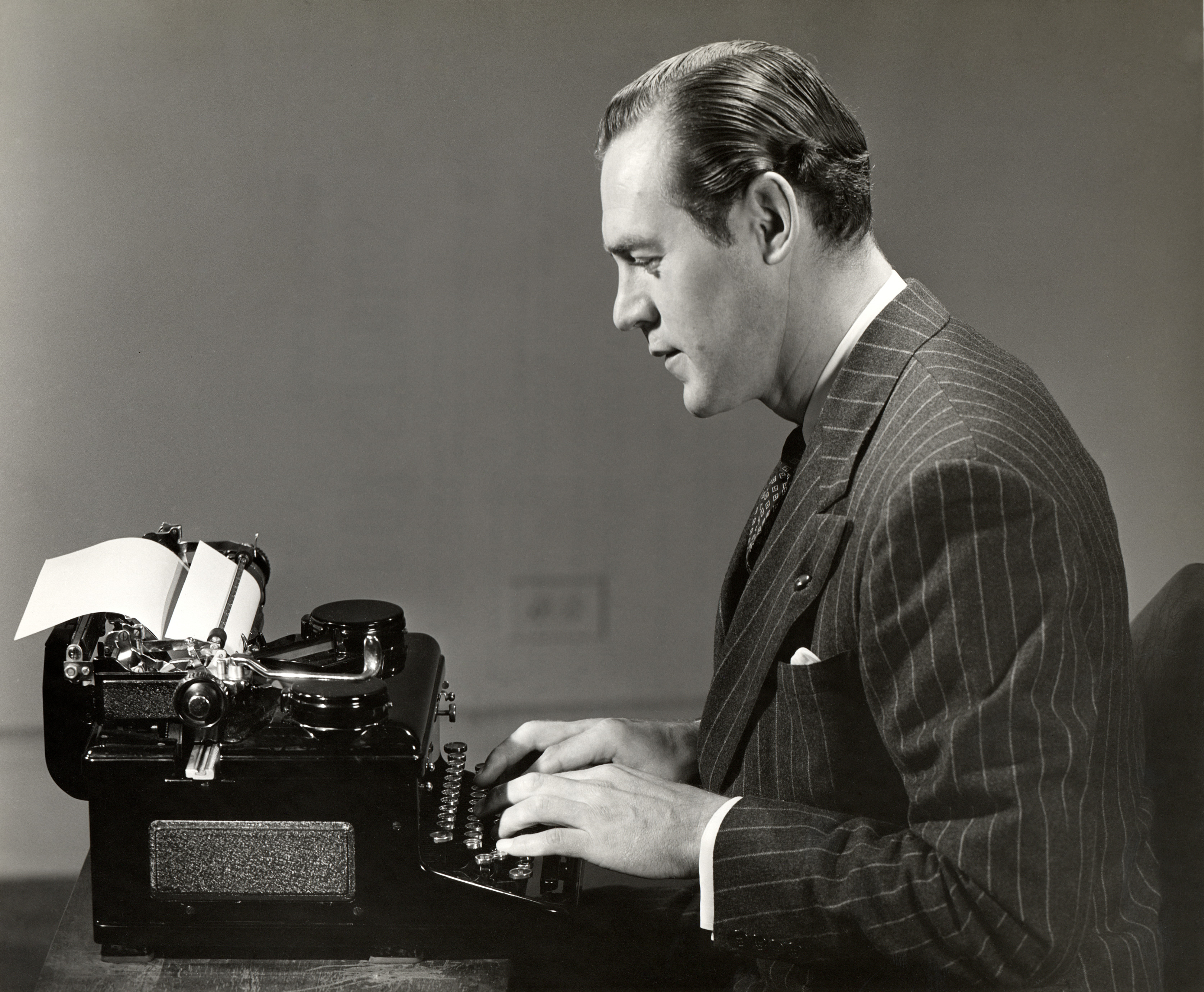
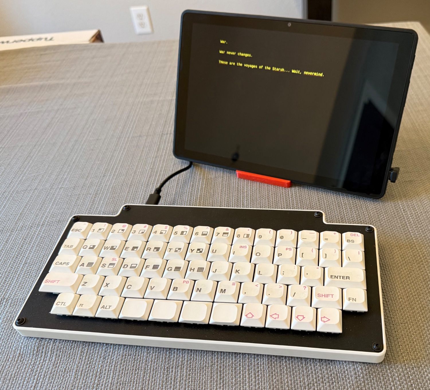
I agree with the general takes here, and can add one for specific situations. I have some very old keyboards, and frankly even my newer ones rely on designs that are over 40 years old. In this particular case, I find the old tech superior, because they simply feel nicer to type on, and that’s what a keyboard is for.
I also have quite a few fountain pens, but whereas with a little effort the keyboards are as good or better than an average modern model, I’ll admit there is a fussiness and mess with fountain pens you have to weigh against the nicer writing experience.
This poll is done online based on selection by address, and they’ll even hand out a tablet if the person at the address doesn’t have internet access. There are undoubtedly still old school polls doing landline cold-calls, but I think they’re growing rarer, and frankly at this point they’re Karoline Leavitt’s favorite ones.
https://www.reuters.com/world/us/how-are-reutersipsos-us-public-opinion-polls-conducted-2024-05-09/
 33·8 days ago
Good for the recall folks, though I’m sure there’s a share of pure NIMBYs in there and some folks definitely having the day they voted for. That’s funny that the supporters think the 1000 construction jobs will be for locals and not the specialized oilfield-like firms that are already staffed up to work these projects, or that Google will have 200 permanent staffers tied to the location and contributing to the town’s tax base.
 25·8 days ago
“Gravity plating!” As long as there is floor, you’re good.
Also, won’t anyone think about the fact that Trump literally makes energy policy based on the fact that he thinks wind turbines are ugly?
Based on the number of anoles, skinks, geckos, and Texas spinys in our yard, I’m guessing that little display was for someone else.

My brother used to catch them and let them bite down on his earlobes.
Weird dude.
 18·12 days ago
However, after a weeks in the role, several FEMA officials said they came around to Phillips after seeing his initiative during the January storm response.
“Gregg Phillips is FEMA’s best hope at this moment. I can’t believe I’m saying that,” one high-ranking FEMA official told CNN at the time.
Same, unnamed FEMA official, same.
Chief Justice has been considered a separate slot for nomination purposes as of the late 19th century, so when he retires or croaks, the job will come open. Sometimes the then-president nominates one of the existing justices and backfills, but it’s completely possible, as @[email protected] says, to directly nominate the new person for chief justice; it’s actually pretty common to do so.
Once again, I will mention that “originalism” and “textualism” were a fucking death knell for jurisprudence, which barely withstood Bush et al, to say nothing of a brazen bad actor like Trump. They are the dark side of legal reasoning: quicker, easier, more seductive, but once you go down that dark path (with a ritually worshipped constitution that was a nice bit of kit for its time and place but is maddeningly vague and almost impossible to amend), forever will they dominate your destiny.
It’s impractical and deeply, inherently regressive to think that a few clever slaveholding provincials had everything figured out forever and ever (see also the almost impossible to amend part), and pretending that it’s workable without applying thought and context should be grounds to get someone disbarred.
While they’ve got it apart, they can make sure to use a high quality battery!
 10·14 days ago
Experts report the alloy was unmoved by the masterful prologue to Pixar’s 2009 classic Up.
 5·14 days ago
I don’t know what kind of vibe I’m giving off, but I always seem to get the “Deepstate, amiright?!” drivers. Okay, that’s a lie… I do know my vibe… I live in a Texas suburb and I’m a cishet white guy who wears cargo shorts and dadcaps and likes sports.
I hate it, but still, this person is taking me somewhere I need to be so I want to be nice, but I can’t quite bring myself to pretend to agree. Unfortunately, a polite “Oh, I’m not sure I’m sold on that” just gets them helpfully trying to probe, “so why would Kamala do a pizzagate if she weren’t a lizard person?”
Fuck me, I need some tattoos.
 36·15 days ago
That one’s not actually a problem. The flag is always “hoist side forward” to symbolize a no-retreat mentality. We shall ignore Vietnam and Afghanistan, and how that goes in the reign of President “why they no helping me?!?” remains to be seen.


This is the rub. Can he officially? No. But then, he can’t officially rename the Department of Defense either. What they can do is go in arrears on payments and refuse to cooperate with allies or acknowledge that a given incident involves treaty obligations, and be extremely open about all of it. The only thing the law does is give the next guy cover to walk things back because it was never formal, but by then 99% of the damage will have been done.
Just from a sheer nuts and bolts point of view, the foreign relations damage is going to take literally decades to undo, including at least 8 years of republican administrations that top out at George W Bush levels of fascist exceptionalism. No sane government would trust the US with long-term commitments otherwise.